3D finder: Simple zero point determination and measurement
The 3D finder, also known as 3D touch probe, is a tool that is used specifically for zero point determination and measurement on CNC machines. This article first explains how to calibrate the 3D finder on a CNC machine with cncGraF and then describes how it can be used efficiently.

Overview
1. what do I need to be able to use the 3D Finder optimally?
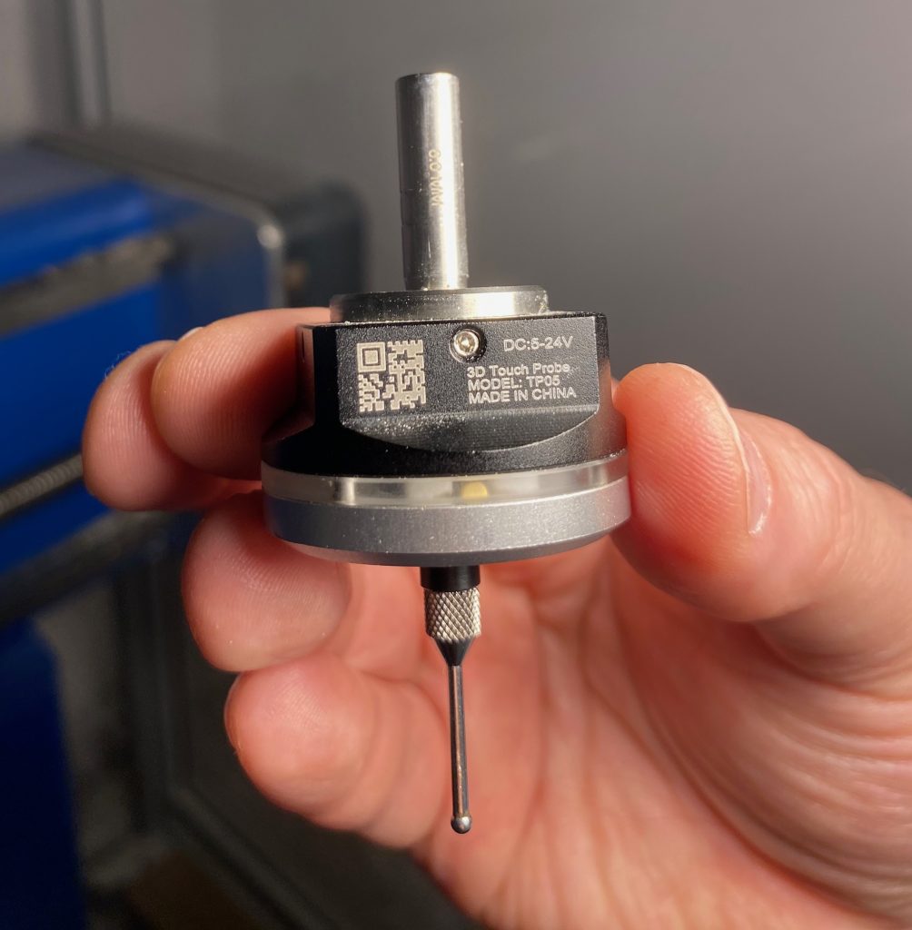
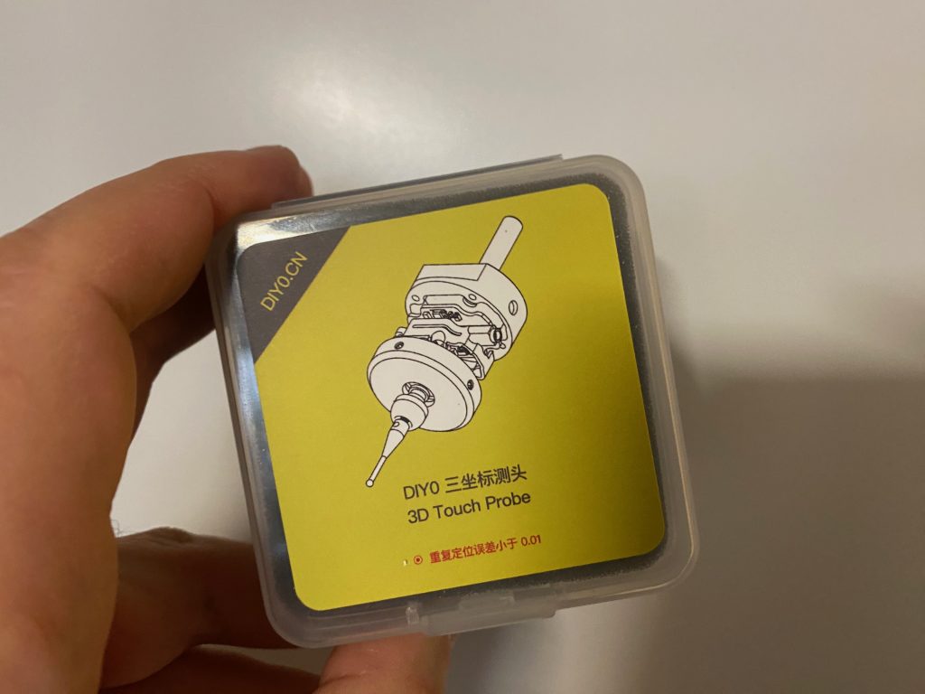
To use a 3D finder, you first need the device itself, of course. There is a wide range of 3D finders on the market, with prices varying from cheap to expensive. Personally, I use an inexpensive 3D measuring probe from China.
Additional equipment: Tool length sensor
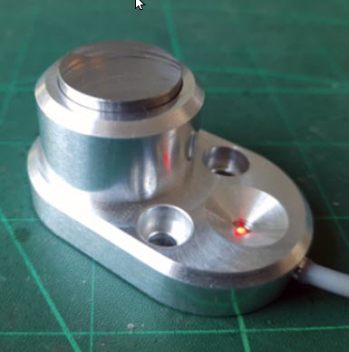
In addition, a tool length sensor is required. This sensor is permanently mounted at one point on the machine.
It is essential for the automatic determination of the Z zero point.
In combination with the 3D finder, the tool length sensor enables fully automated determination of the Z zero point.
2. assembly and preparation of the 3D measuring probe
The 3D finder must be mounted next to the milling cutter on a fixing rail. By lowering the 3D Finder onto this rail - whether manually or automatically - the device is ready for use. It is essential that the 3D finder is always lowered lower than the longest milling cutter and is always set to the same position.
3. calibration of the 3D measuring probe with cncGraF
Calibrate tool length sensor
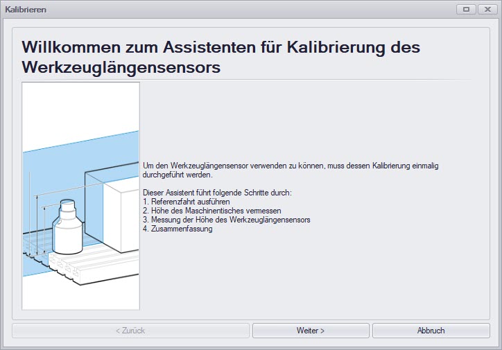
Firstly, the tool length sensor must be calibrated in cncGraF. Calibration is easy with the wizard in the menu „Move -> Tool length sensor -> Calibrate“. Simply follow the instructions step by step.
![]() Note: If your tool length sensor is already calibrated, this step can be skipped.
Note: If your tool length sensor is already calibrated, this step can be skipped.
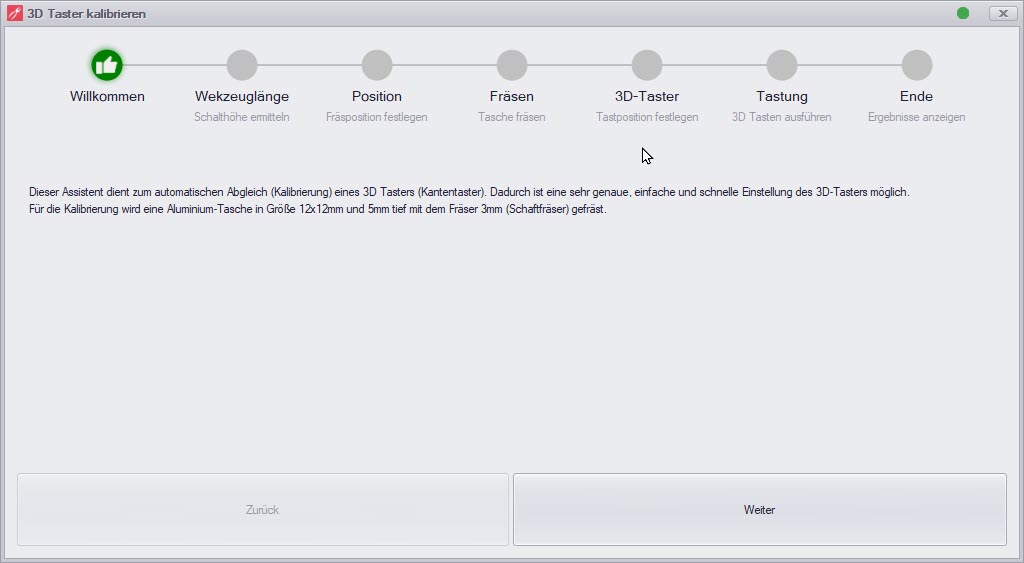
Calibrate 3D measuring probe
The 3D measuring probe is also conveniently calibrated with an assistant. To do this, a small pocket is milled from aluminium or another material with the dimensions 12x12mm and a depth of 5mm using a 3mm end mill. The edges of the milled pocket are then scanned with the 3D finder.
Checking the measurement results
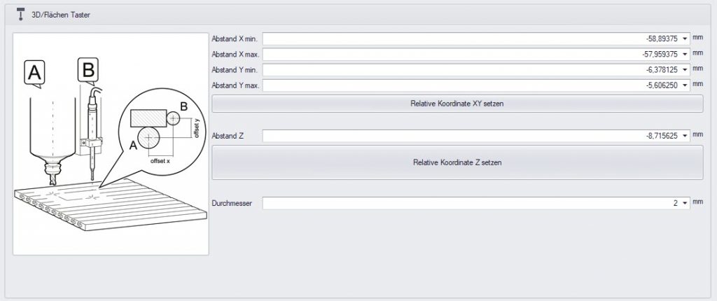
The measurement results can be viewed under „Machine parameters -> Sensors“ in the cncGraF control software.
As the screenshot below shows, the deviations at the tip of the probe are almost 1 mm in both X+/X- and Y+/Y-. This illustrates that it is almost impossible to mount the 3D probe in such a way that it does not show any deviations.
The length of the probe and its mounting contribute to the fact that even minimal inaccuracies in the mounting „add up“ at the tip of the probe.
Advantages of this method
This method makes it possible to identify deviations along the X (for movements in X+ and X-) and Y axes (for movements in Y+ and Y-). These deviations are then automatically corrected during edge detection and calculations, resulting in a significant improvement in measurement accuracy.
4. use of the 3D touch probe in the cncGraF software
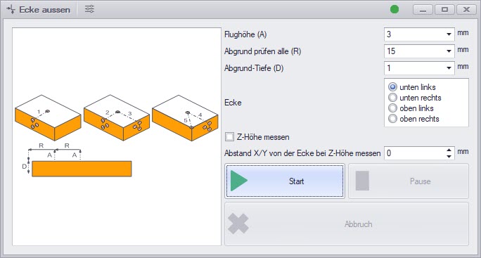
The 3D touch probe is operated in the cncGraF software via integrated dialogues. The following functions are implemented:
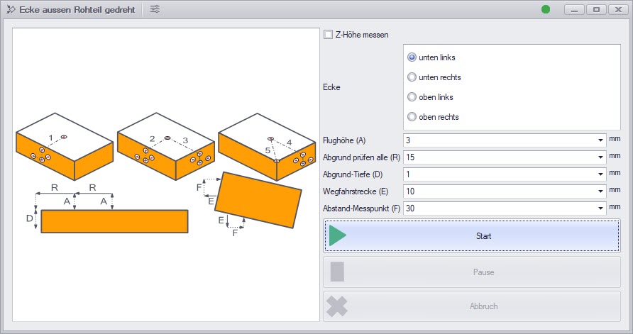
- Determination of the outer corners including Z-height
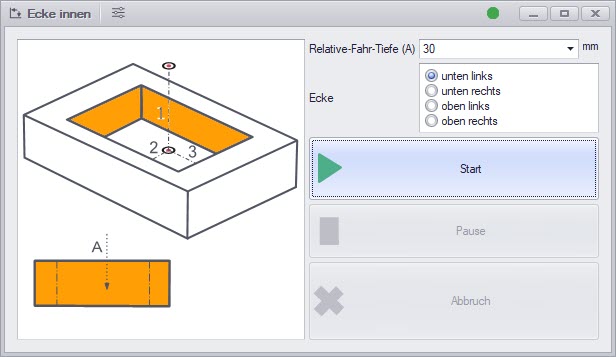
- Determining the inner corners
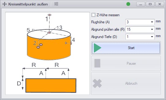
- Determination of the outer centre of the circle including Z-height
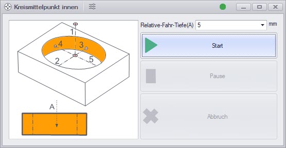
- Determining the centre of the circle inside
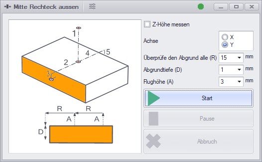
- Determining the centre of a rectangle outside including Z-height
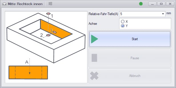
- Determining the centre of a rectangle inside
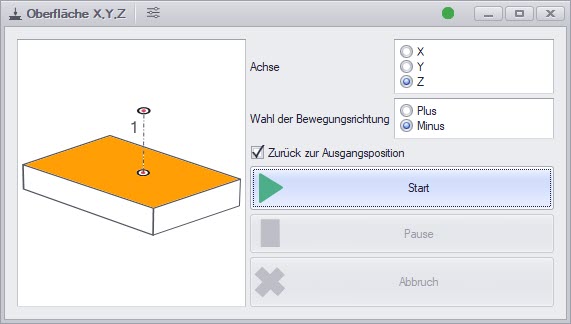
- Surface measurement in the X, Y and Z axes
- Scanning the outer corner and the side: Based on the values determined, the drawing is positioned so that it corresponds to the alignment of the material on the machine.
Screenshots of the various dialogues can be found in the gallery below.
![]() Tip: Checking the 3D Finder before touching it
Tip: Checking the 3D Finder before touching it
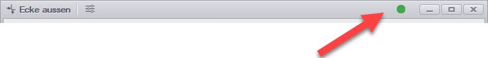
Before the scanning process is started, you can check the functionality of the 3D finder.
In each dialogue window for these functions, the status of the input is shown by a green round dot. If you press the 3D finder with your finger, the status should change (the green dot goes out or lights up).
5. use measurement results for zero point determination
The measurement results can be used to determine the zero point either automatically or manually. For manual zero point determination, the dialogue window „ Set zero point ![]() “ must be called up after the successful measurement. In this dialogue, the option „Last scan position“ is active and already preselected in the „Coordinates“ option selection group for existing measurement results.
“ must be called up after the successful measurement. In this dialogue, the option „Last scan position“ is active and already preselected in the „Coordinates“ option selection group for existing measurement results.
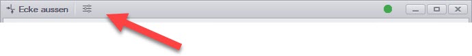
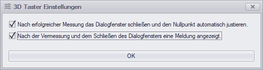
Automatic zero point determination can be activated. The corresponding option can be found in the window frame of every dialogue relating to measuring with the 3D measuring probe.
6. summary
We hope that this guide has provided you with helpful information on using the 3D touch probe and the cncGraF software for zero point determination and measurement.
Yours sincerely, Your BOENIGK-electronics Team