Setting up and using the spindle speed
for the CNC machine
In this article, I will describe how to connect and test the hardware for the spindle speed.
I will also explain how the speed can be activated and used using the cncGraF software.
Before we start setting up the speed, however, we first need to clarify which hardware components are required to use the speed.
Overview
1. what do I need for the spindle speed control?
- Frequency inverter with matching spindle motor: A frequency inverter, also known as an inverter or frequency converter, is an electronic device that changes the frequency and voltage. It is required to control the speed of the spindle.
- Interface card DAC-INT-10V or CAN Expansion DAC 0-10V: These cards have an analogue output in the range of 0-10 volts as well as a switching signal. Both connections are required to transmit the corresponding control commands to the frequency inverter.
2. setup: connect hardware
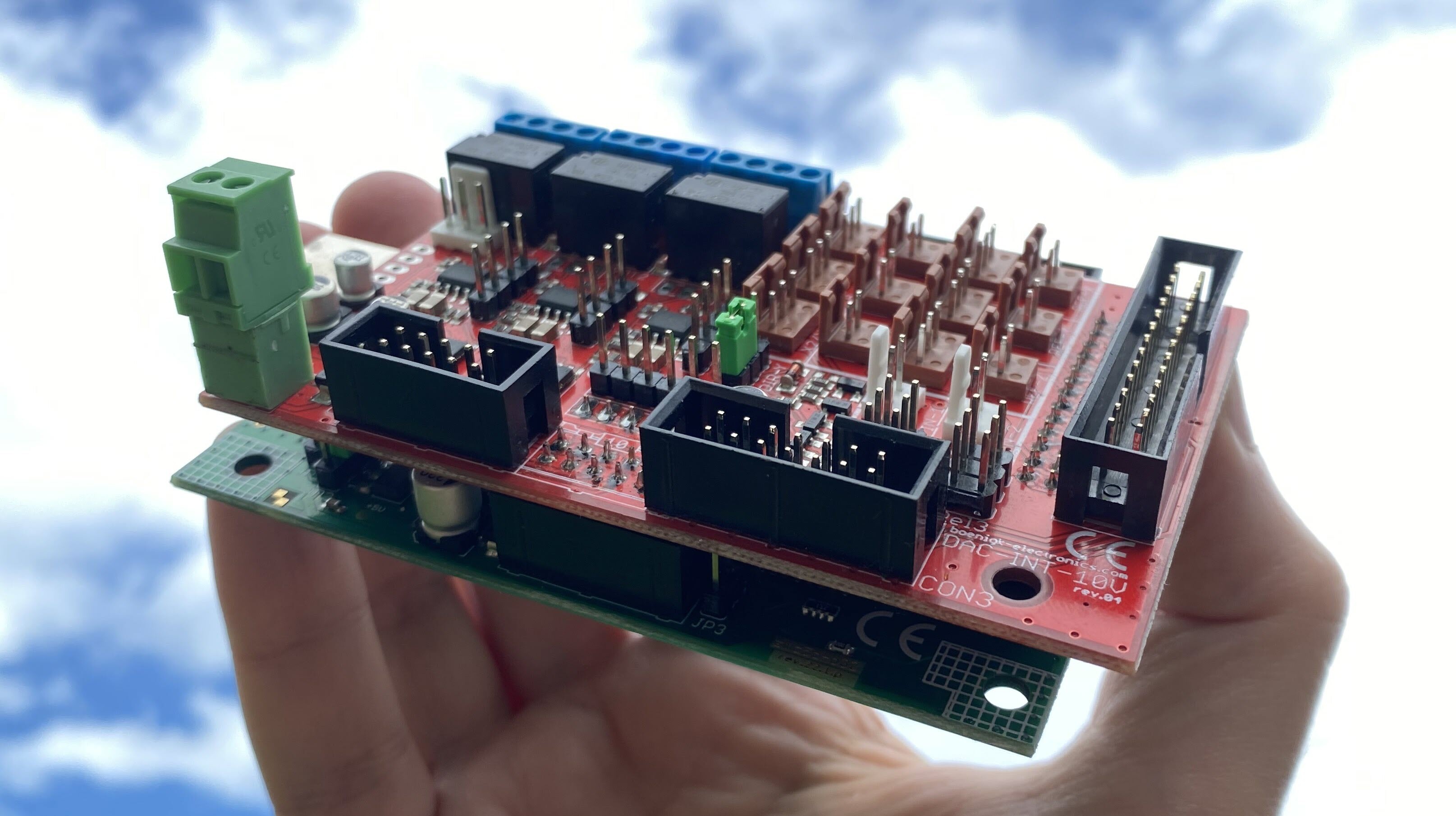
The first step is to install the interface card.
The DAC-INT-10V interface card is required for the smc5d-p32 or smc5d-m4 lan CNC controller,
while the control cabinet version CAN Expansion DAC 0-10V is required for the smc5d-m4 pro.
The DAC-INT-10V interface card for CNC controllers smc5d-p32 and smc5d-m4 lan
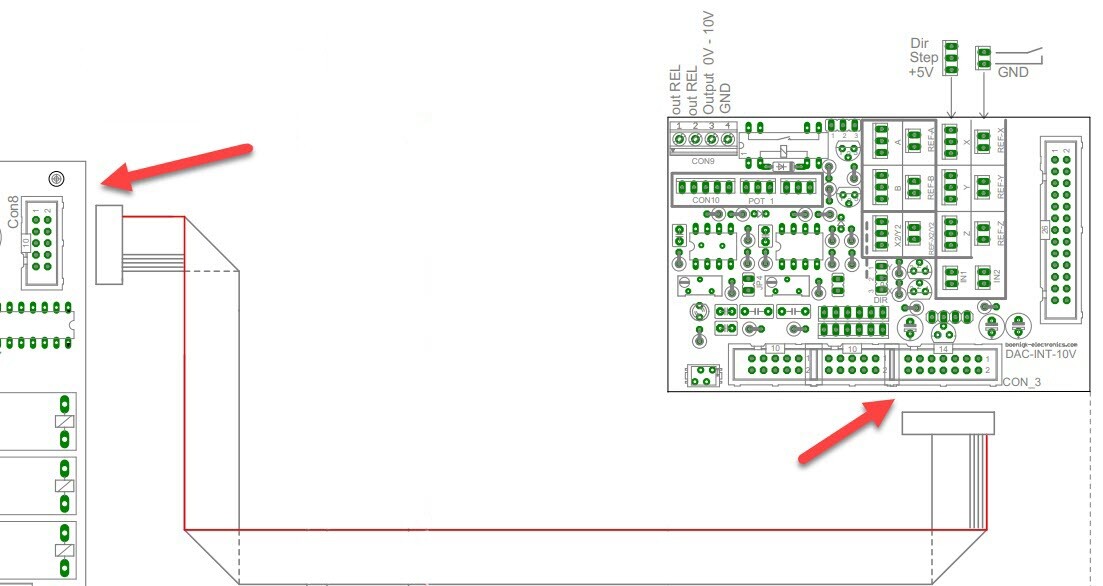
The DAC-INT-10V interface card is plugged into the CNC controller, either the smc5d-p32 or the smc5d-m4 lan.
The DAC-INT-10V interface card can be supplied with +24 volts in two different ways: via the external connection (green connection) or via the pins on CON3 (ribbon cable). The variant via CON3 is usually used together with a relay card, where the +24 volts come from the relay card.![]() Note: The +24 volt power supply is required for the 0-10 volt analogue output.
Note: The +24 volt power supply is required for the 0-10 volt analogue output.
The DAC-INT-10V interface card can also be supplied with 5 volts. The 5 volts are used to supply the CNC controller with power externally (not via the USB interface).
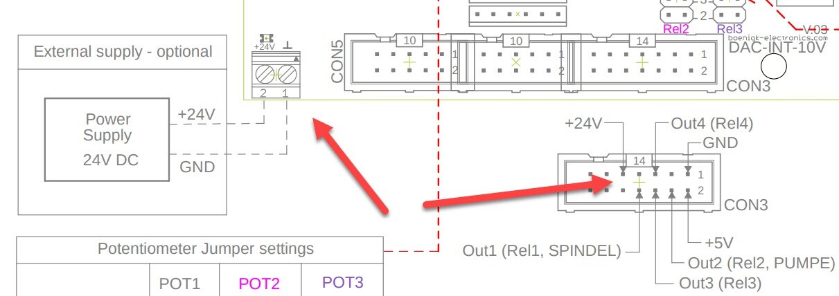
or via the pins on CON3
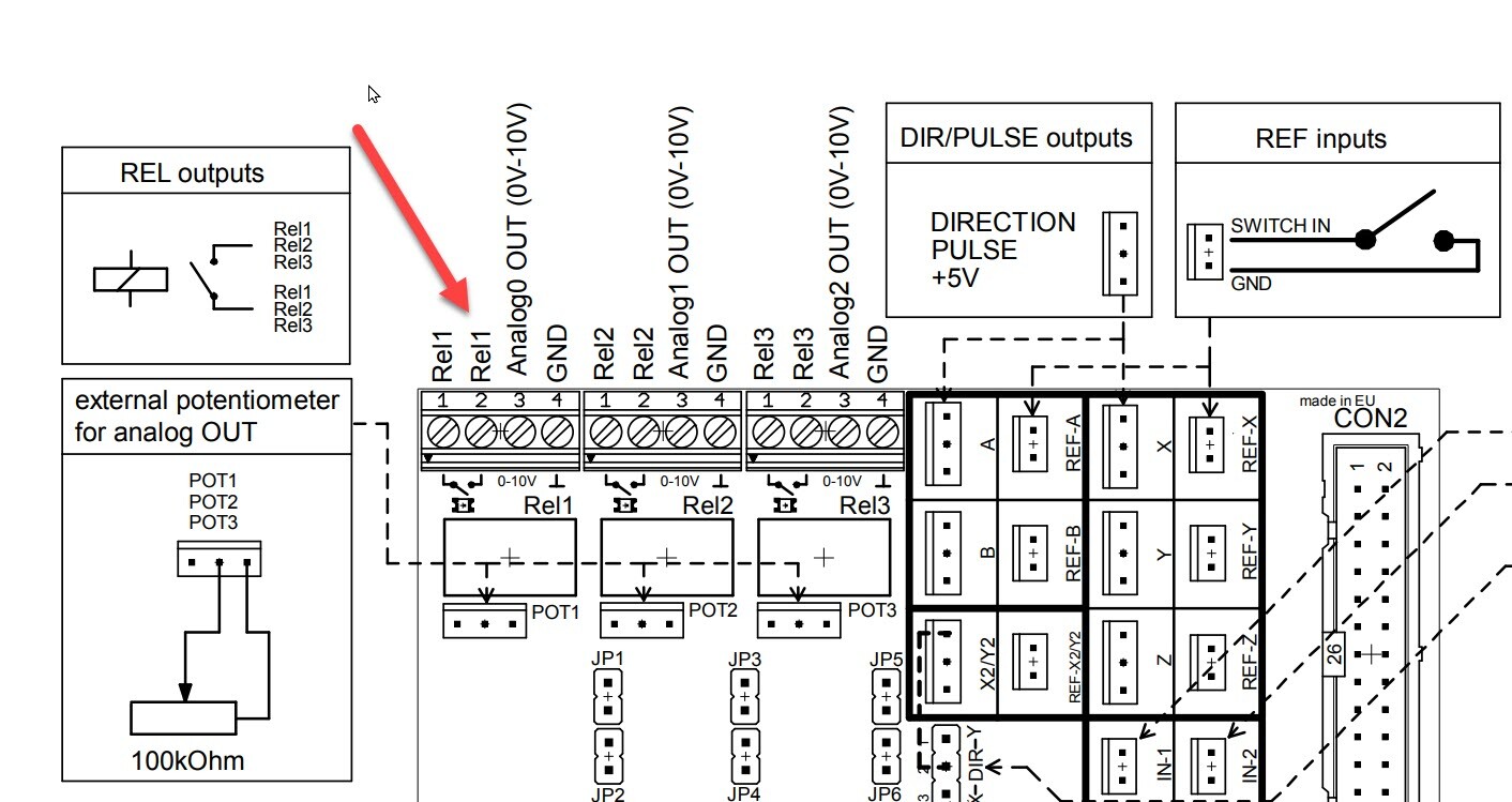
Finally, the frequency inverter must be supplied with 0-10 volts and a switching signal. The connections in the corner of the DAC-INT-10V interface card are used for this purpose.
The switching signal: The two connections Rel1 and Rel1 connect the plugged cables, whereby the connection is only made when output 1 for the spindle is switched in the cncGraF software.
This completes the hardware connection. The spindle speed can now be switched on and tested in the cncGraF software. Make sure that all connections are correct and secure before carrying out the test.
 Download - Documentation
The CAN Expansion DAC 0-10V expansion card
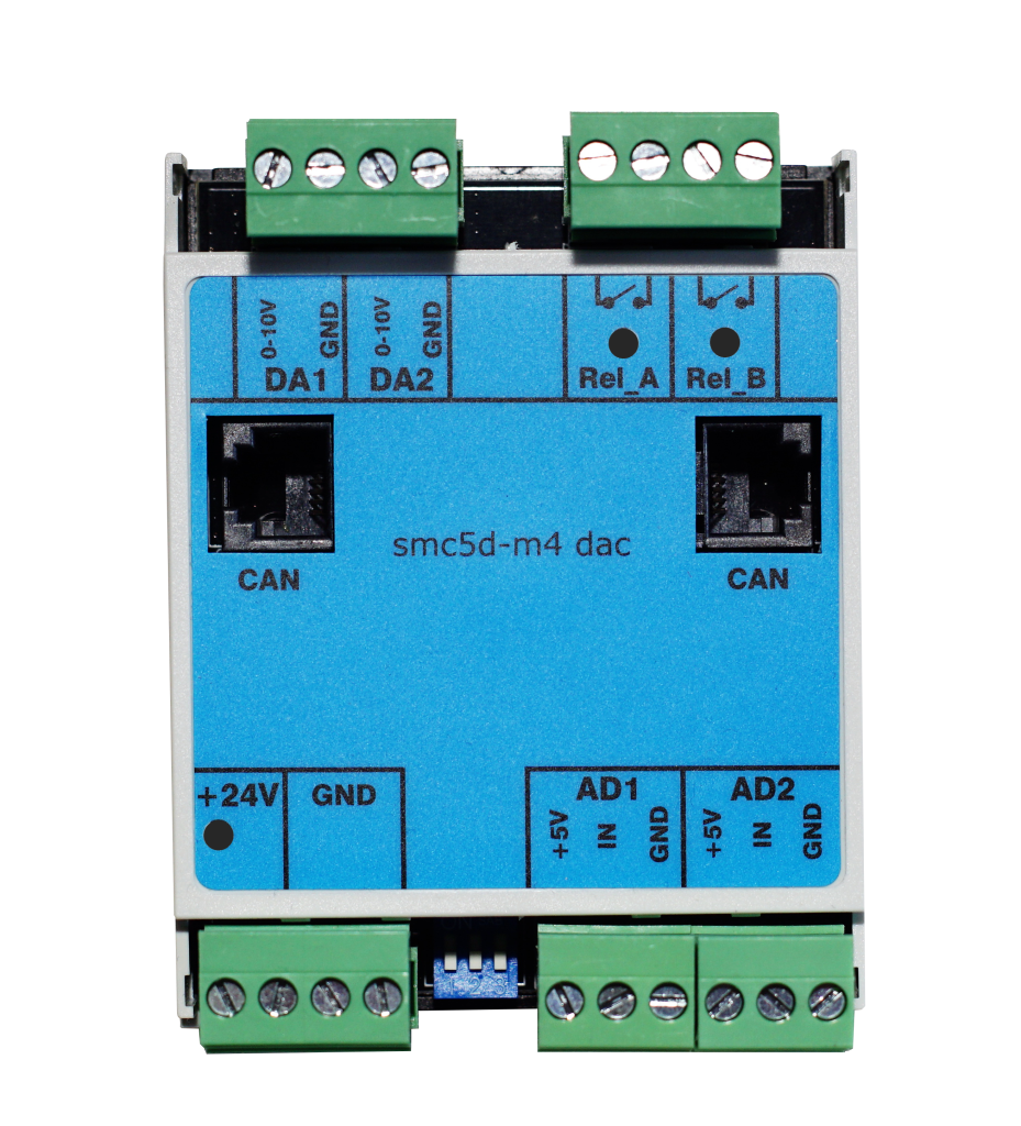
The CAN Expansion DAC 0-10V expansion card is required when using the smc5d-m4 pro CNC controller for top-hat rail mounting. It is connected via a CAN cable supplied. The +24 V power supply is provided via the green connection at the bottom left (see image below).
The switching signal: The two Rel_A connections connect the plugged cables, whereby the connection is only made when output 1 for the spindle is switched in the cncGraF software.
This completes the hardware connection. The spindle speed can now be switched on and tested in the cncGraF software. Make sure that all connections are correct and secure before carrying out the test.
3. set-up: setting up the software
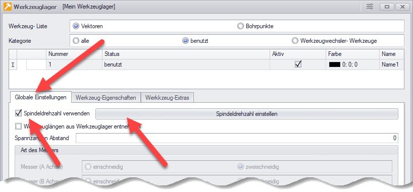
The spindle speed is activated in cncGraF in the tool storage menu (see image below). You can access this function either via the main menu „Settings -> Tool storage“ or by simply clicking on the tool storage symbol.

Click on the „Global settings“ tab in the Tool store dialogue. The spindle speed function can be found there. Click on the „Use spindle speed“ checkbox to activate the spindle speed. Next to the checkbox you will find the „Set spindle speed“ button. Click on this button to open the dialogue window for setting the spindle speed.
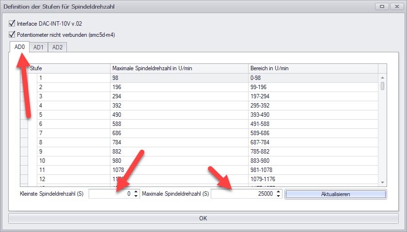
The dialogue window „Definition of steps for spindle speed“ appears. Set your speed range there, starting with the lowest speed 0. In the image below, the speed range is set from 0 to 25000. Please refer to the operating instructions for your spindle for your speed range. Please note that the range is set in the AD0 tab. The AD1 and AD2 tabs are intended for other analogue outputs.
The „Interface DAC-INT-10V v.02“ checkbox should remain ticked. This option should only be unchecked if you have an older version than v.02. The older interface cards were imprecise in the 0-10 volt range. Not activating the checkbox activates an algorithm that compensates for this inaccuracy.
The settings for the speed control have been finalised. The first test can now be carried out.
4. test spindle speed
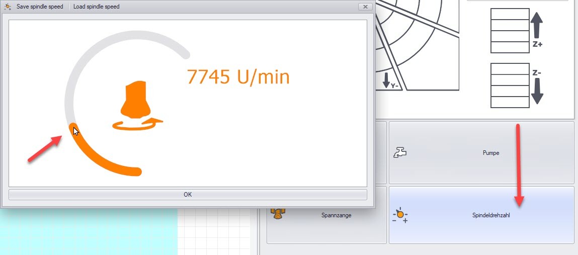
The spindle speed can now be tested. To do this, perform the test in the „Manual movement“ window, which is normally docked on the right. If this window is not visible, you can display it in the main menu by selecting „Window -> Move manually“.
In the „Move manually“ window, you will find the „Spindle speed“ button. However, first click on the „Spindle“ button to switch on the spindle and then on the „Spindle speed“ button. The dialogue window for the spindle speed then appears. In this dialogue window, you can change the speed by clicking and holding on the graphic. The spindle speed is adjusted accordingly.
![]() Hinweis: Da das „Manuell Bewegen“-Fenster individuell anpassbar ist, könnte es sein, dass dieser Button nicht vorhanden ist. In diesem Fall müssen Sie den Button für die Spindeldrehzahl einblenden lassen. Gehen Sie dazu mit der Maus in das „Manuell Bewegen“-Fenster irgendwo zwischen die Elemente und klicken Sie die rechte Maustaste, um das Kontextmenü aufzurufen. Wählen Sie „Customize Layout“ aus. In dem Dialog „Layout Customization“ suchen Sie nach dem Button „Spindle Speed Button“ und ziehen Sie diesen per Drag-and-Drop in das „Manuell Bewegen“-Fenster ein.
Hinweis: Da das „Manuell Bewegen“-Fenster individuell anpassbar ist, könnte es sein, dass dieser Button nicht vorhanden ist. In diesem Fall müssen Sie den Button für die Spindeldrehzahl einblenden lassen. Gehen Sie dazu mit der Maus in das „Manuell Bewegen“-Fenster irgendwo zwischen die Elemente und klicken Sie die rechte Maustaste, um das Kontextmenü aufzurufen. Wählen Sie „Customize Layout“ aus. In dem Dialog „Layout Customization“ suchen Sie nach dem Button „Spindle Speed Button“ und ziehen Sie diesen per Drag-and-Drop in das „Manuell Bewegen“-Fenster ein.
5. troubleshooting
If the speed does not work, the following points should be checked:
Check the +24 volt power supply for the interface card
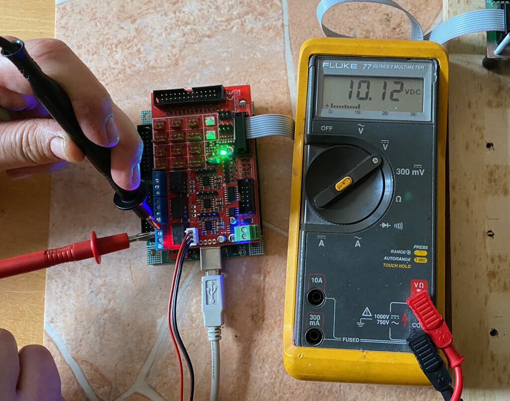
This can be checked with a voltmeter. All you need to do is measure the DC voltage at pins 3 and 4 (see image below). During the measurement process, the spindle speed must of course be adjusted in the software at the same time.
Check the switching signal (output 1) for spindle switching
To do this, the setting for the spindle must be checked in the ‚Machine parameters -> Pin assignment‘ menu. The spindle must have output 1 for the DAC-INT-10V interface card. When the spindle is switched (output 1), a red diode lights up on the DAC-INT-10V.
![]() Hinweis: Der häufigste Fehler ist die fehlende Stromversorgung von +24 Volt.
Hinweis: Der häufigste Fehler ist die fehlende Stromversorgung von +24 Volt.
6. use
The spindle speed setting in the cncGraF software varies depending on the file type.
For 2D file formats such as DXF or HPGL, the spindle speed is set in the „Tool storage“ dialogue. This is because DXF and HPGL files do not have the command for the spindle speed.
G-code files, on the other hand, contain an ‚S‘ command for the spindle speed. The speed is therefore taken from the G-code file. The setting for the speed in G-code files is then made in your CAD/CAM software.
![]() Note: Preheating the spindle of the CNC machine reduces the load on its components. This means that the spindle can last longer and is less susceptible to repairs.
Note: Preheating the spindle of the CNC machine reduces the load on its components. This means that the spindle can last longer and is less susceptible to repairs.
In this video, I show how to set up the „Spindle warm-up“ function for CNC machines in cncGraF 8.
We hope that this article has been helpful to you in handling the spindle speed. If you have any questions, please do not hesitate to contact us.
Yours sincerely, Your BOENIGK-electronics Team