CNC programming:
Learn G-code - Quick and easy
G-code is a computer language that is used to control CNC machines. CNC stands for Computerised Numerical Control, which means that machines are controlled by computers.
In modern manufacturing, G-code is generated automatically by CAD/CAM software, which means that manual programming of G-code is rarely necessary. Nevertheless, it is important to know the basics of G-code programming. In particular, there are the following reasons for this:
- Manual adjustment of the G-code: In production, simple parts are often manufactured that differ only slightly from one another. In such cases, it is advantageous to programme and adapt the G-code manually in the text editor. This saves time, as a new G-code file does not have to be generated using CAD/CAM software for every small variant or customisation.
- Troubleshooting and optimisation: An understanding of G-code programming enables CNC operators to quickly recognise and rectify errors in the programmes. If a CNC machine does not work as expected, the cause can often lie in the programming details of the G-code. An operator who is familiar with G-code programming can identify and correct such errors independently.
- Post-processor customisation: Sometimes it is necessary to adapt the post-processor in the CAD/CAM software to output the G-code, as the automatically generated G-code does not meet the requirements. In such cases, basic knowledge of G-code is advantageous.
In this blog article, you will learn the basics of G-code. You will then be able to write your own simple G-code programmes and solve the above-mentioned problems independently.
Learning G-Code Part 1/2: Basics
What do I need for G-code programming?
The G-code consists of a series of text instructions that are stored in a text file (ASCII file). The CNC machine executes these commands in the sequence from the beginning of the text file to the end.
Only a text editor is required for CNC programming and G-code. However, as a visual check of the programmed G-code is necessary, a CNC simulation must be used.
Free G-code simulator: cncGraF
The CNC control software cncGraF is ideal for training purposes: It offers a built-in G-code simulator and CNC machine emulator, is free of charge (freeware) and does not require a real CNC controller.
Click here to download cncGraF free of charge.
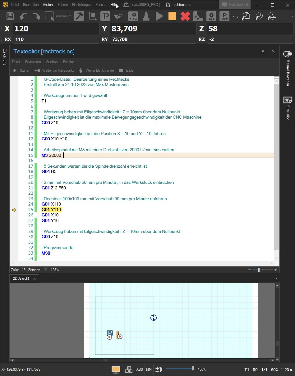
The screenshot below presents CNC control cncGraF, including the G-code text editor and the 2D view. The CNC machine emulator is switched on and the G-code file is executed in emulator mode.
To find out more, click on the blog article
cncGraF: Free G-code simulator and CNC machine emulator.
Structure of a G-code file
The following example of a G-code file is available:
; G-code file: Production of a rectangle, created on 24/10/2023
; Activate tool number 1
T1
; Lift the tool at rapid speed to the height Z = 10 mm above the zero point
G00 Z10
; Move to position X = 10 and Y = 10 at rapid speed
G00 X10 Y10
; Switch on the work spindle with M3 at a speed of 20000 rpm
M3 S20000
; Wait 5 seconds until the spindle speed is reached
G04 H5
; plunge 2 mm into the workpiece at a feed rate of 600 mm per minute
G01 Z-2 F600
; Traverse rectangle 100×100 mm at a feed rate of 600 mm per minute
G01 X110
G01 Y110
G01 X10
G01 Y10
; Lift the tool at rapid speed to the height Z = 10 mm above the zero point
G00 Z10
; End of programme
M5 M30
This G-code describes the machining of a rectangle with a CNC machine. The G-code begins with comments that are separated by a semicolon (;) are labelled. These comments are not relevant for the machine, but help the operator to understand the code.
- Tool selection: First, tool 1 is selected with the command
T1selected. - Positioning of the tool: The command
G00 Z10lifts the tool to 10 mm above the zero point of the machine.G00the machine travels at rapid traverse, i.e. at maximum speed. - Moving to the start position: The machine runs with
G00 X10 Y10to position X=10 Y=10. - Switch on the spindle: With
M3 S20000the spindle is switched on and set to 20000 revolutions per minute. - Waiting time: The command
G04 H5ensures that the machine waits 5 seconds for the spindle to reach the desired speed. - Immerse yourself in the material: With
G01 Z-2 F600the tool plunges 2 mm deep into the material at a feed rate of 600 mm per minute.G01is used for the milling movements. - Rectangular machining: The next commands (
G01 X110,G01 Y110,G01 X10,G01 Y10) move the tool to mill a 100×100 mm rectangle. - Return to the starting position Z:
G00 Z10lifts the tool back to 10 mm above the zero point. - End of programme: The command M05 switches the spindle and the command M
30ends the programme.
G-Code: Circles and arcs
Next, we extend our example with a circular milling that must be carried out before the rectangle. The extended and modified G-code lines are colour-coded in Light red highlighted. The G-code then looks like this:
; G-code file: Production of a rectangle, created on 24/10/2023
; Tool number 1 is selected
T1
; Lift the tool at rapid speed to the height Z = 10 mm above the zero point
G00 Z10
; Move to position X = 10 and Y = 10 at rapid speed
G00 X10 Y10
; Switch on the work spindle with M3 at a speed of 2000 rpm
M3 S2000
; Wait 5 seconds until the spindle speed is reached
G04 H5
; Move to the centre of the rectangle
G00 X60 Y40
; plunge 2 mm into the workpiece at a feed rate of 600 mm per minute
G01 Z-2 F600
; Circle (d=20mm, centre 60×60) clockwise
; with feed 600 mm per minute drive
G02 I60 J60 X60 Y40
; Lift tool at rapid speed : Z = 10mm above the zero point
G00 Z10
; Move to position X = 10 and Y = 10 at rapid speed
G00 X10 Y10
; plunge 2 mm into the workpiece at a feed rate of 600 mm per minute
G01 Z-2
; Traverse rectangle 100×100 mm at a feed rate of 600 mm per minute
G01 X110
G01 Y110
G01 X10
G01 Y10
; Lift tool at rapid speed : Z = 10mm above the zero point
G00 Z10
; End of programme
M5 M30
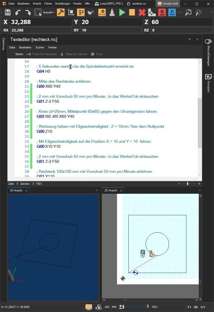
The G-code simulator (see screenshot) shows a rectangle and a circle placed in the centre of the rectangle.
![]() Important: If the drawing is not displayed correctly, this may be due to the incorrect setting for the G02/G03 circle (arc) commands. The G02/G03 commands can be interpreted as relative or absolute. This example refers to G02/G03 in absolute form. In this case, the „G02/03 relative“ option must be deactivated in the cncGraF G-code simulator in the main menu „Settings → Options → File → G-code“.“
Important: If the drawing is not displayed correctly, this may be due to the incorrect setting for the G02/G03 circle (arc) commands. The G02/G03 commands can be interpreted as relative or absolute. This example refers to G02/G03 in absolute form. In this case, the „G02/03 relative“ option must be deactivated in the cncGraF G-code simulator in the main menu „Settings → Options → File → G-code“.“
G-Code: Sheet command G02/G03
The G02 command is used to programme a circular or arc-shaped movement in a clockwise direction. Command G03 does the same, but in an anti-clockwise direction.
The G02 command in the G code has the following syntax:
G02 X... Y... I... J...
It says:
- ‚G02‚ for the command itself, which represents a clockwise arc. The last position of the previous G-code command is the start position of the circle or arc.
- X... and Y... indicate the end coordinates of the circle or arc.
- I... and J... indicate the distance from the current point to the centre of the arc on the X and Y axes.
G00 X60 Y40 ; This is the start position X,Y of the arc.
G02 I60 J60 X60 Y40 ; This command moves the tool in a clockwise arc.
- I60 J60: These are the coordinates of the centre of the circle relative to the current position
X = 60 Y = 40 In this case, the centre point is at X = 60, Y = 60. - X60 Y40: These are the end coordinates of the arc. The tool moves to the point X = 60, Y = 40.
- The diameter of the circle (d = 20 mm) is determined by the position of the tool and the coordinates of the centre point.
Table with the most important G-code commands
In this example, you have learnt the basic G-code commands: G01 and G00 for simple movements, the arc command G02, switching the spindle on and off with M03 (and M05), the ‚S‘ command for the spindle speed, the tool number command ‚T‘, G04 for waiting times, ‚F‘ for the working speed and M30 for the end of file. These commands form the basis and are already sufficient for writing your own simple G-code programmes.
Below you will find a tabular overview of all the most important G-code commands.
Command overview of the most important G-code commands
The tabular list of G commands (G code) contains only those commands that are suitable for manual programming as they are easy to use. The complete list of all G-code commands can be found in the cncGraF CNC simulator in the online help [F1 key].
| G-Code | Description of the |
|---|---|
| ; () | The comments are closed with a semicolon ‚;‚ or with brackets ‚()‚ is labelled. The comments are ignored by the CNC machine. Example: (Move to position Z10) G00 Z10 ; Move to position Z10 G00 Z10 |
| N | N for record number (optional) Example: ; Record number is not necessary. N10 T1 M3 S2501 |
| F | F for feed rate in mm/min Example: ; travel at 300 mm/min G01 X100 Y10 F300 |
| T | T for tool number Example: ; Tool 1 is active T1 |
| M03 S | M03 switches the spindle on, S defines the spindle speed in rpm Example: ; Spindle is switched at 2000 revolutions per minute M3 S2000 |
| D | D Tool diameter in millimetres. Example: ; Diameter 2.5 mm. D must be directly behind T T1 D2.5 |
| G00 | With G00 the machine travels at rapid traverse, i.e. at maximum speed. The tool is not in the material (empty run). Example: ; Position X = 100 Y = 10 Start up G00 X100 Y10 |
| G01 | With G01 the programmed path is travelled at the milling speed (feed speed ‚F‘). This path is visualised as a vector in the cncGraF G-code simulator. Example: ; Position X = 100 Y = 100 with 300 mm/min Start up G01 X100 Y10 F300 |
| G02/G03 | G02 Circle (arc) clockwise, G03 Circle (arc) anti-clockwise. Parameters: X Y I J K X End coordinate in X direction Y End coordinate in Y direction I Centre point in X direction J Centre point in Y direction K Centre point in Z direction Example: G00 X10 Y10 F100 G01 Z-2 F50 ; Move in an arc from X10, Y10 to X30, Y10 with the centre point I20 and J10 G02 I20 J10 X30 Y10 |
| G04 H | With G04 a dwell time is programmed. Parameters: H - Specification of the time in seconds Example: ; Waiting time 2.5 seconds. This command instructs the CNC machine to ; to pause for the specified time before executing the next command. G04 H2.5 |
| G70/G71 | With G70 and G71 the dimensioning of the coordinates is defined between inches (G70) and millimetres (G71). If not specified, G71 is active. Example: ; Dimensioning of the coordinates is in millimetres G71 |
| G80/G81/G82 | The drilling cycle G81/G82 is suitable for simple drilling and drilling with dwell time. The drilling cycle is started with the command G80 or by another G command such as. G00 or G01 deleted. Format: G98(G99) G81(G82) X Y Z R F (P) Parameters G81 X - Position X Y - Position Y Z - Depth Z (absolute) R - Incremental value of the retraction plane, in relation to the starting point in the Z-axis F - Feed rate Additional parameters for G82 P - Waiting time in milliseconds (1000ms = 1sec.) at the bottom of the hole With commands G98 and G99 The retraction height to which the tool should move after the drilling cycle is defined. G98 - The starting height (starting height) is approached after the drilling cycle. G99 - the retraction height (defined in parameter R) is approached after the drilling cycle. Example: ; Drilling with dwell time, depth Z = 10mm, waiting 100 milliseconds at the bottom of the hole G98 G82 X10 Y10 Z-10 F300 P100 |
| G90/G91 | With G90 Absolute dimension is activated, i.e. all subsequent coordinate values are specified in absolute dimension. G91 activates the relative dimensioning (incremental dimension). Without specification G90 active. Example: ; Relative dimension (incremental dimension) is set G91 |
Summary
G-code programming for CNC machines is not that difficult. With an understanding of only about ten basic G-code commands, you can already achieve impressive results. Learning G-code is definitely worthwhile as it allows you to better understand and utilise your CNC machines.
I hope this blog article helps you to quickly familiarise yourself with G-code programming.
Learning G-Code Part 2/2: Advanced concepts
In the second part of this series, you will learn how to modify simple G-code files in production by using parameters without having to create a new file. In part 2, we will focus specifically on the commands for subroutines, the G25/G26 loops, the IF statement and the use of parameters.
Click on the blog article „Learning G-Code Part 2/2: Advanced CNC programming“ to find out more.
Yours sincerely, Your BOENIGK-electronics Team