cncGraF: Milling DXF files without CAD/CAM software
In this blog article, you will learn how to mill a DXF file directly using cncGraF. This approach saves you from having to use CAD/CAM software, which saves both time and effort, as these programmes can often be complex and require training.
Overview
What is CAD/CAM software?
CAD/CAM software is used to generate G-code files from DXF files. These are special machine files that CNC machines can read in order to mill the desired workpiece. Many CAD/CAM programmes also offer the option of drawing directly within the software.
Why bypass the CAD/CAM software?
By processing DXF files directly with cncGraF, you can save yourself the use of separate CAD/CAM software. This has the advantage that you do not have to familiarise yourself with often complicated and time-consuming software. This approach is a time-saving alternative, especially for simple projects.
![]() Hinweis: Bitte beachten Sie, dass dieser Ansatz hauptsächlich für relativ unkomplizierte 2,5D-Teile geeignet ist, wie sie häufig vorkommen.
Hinweis: Bitte beachten Sie, dass dieser Ansatz hauptsächlich für relativ unkomplizierte 2,5D-Teile geeignet ist, wie sie häufig vorkommen.
1. select CAD software for the creation of DXF files
In order to start the milling process, a DXF file must first be created. This requires the use of CAD software. Fortunately, there are numerous options on the market, both paid and free.
- Free solutions: If you are just starting out with CAD or have a limited budget, LibreCAD, QCad or FreeCAD could be good options. These offer solid basic functions for creating DXF files.
- Paid solutions: If you are willing to buy CAD software, then there is paid software such as Turbocad, Megacad, AutoGrav, Fusion 360 and many more.
- Other software: DXF drawings can also be created in graphic design programmes such as Corel Draw.
![]() Hinweis: Verwenden Sie am besten ein CAD-Programm, das Sie bereits kennen, oder eine Software, die einfach zu erlernen ist. Dies kann den Prozess erheblich vereinfachen, besonders wenn Sie noch keine Erfahrung mit CAD-Programmen haben.
Hinweis: Verwenden Sie am besten ein CAD-Programm, das Sie bereits kennen, oder eine Software, die einfach zu erlernen ist. Dies kann den Prozess erheblich vereinfachen, besonders wenn Sie noch keine Erfahrung mit CAD-Programmen haben.
2. observe the drawing rules
To ensure that the DXF file can be processed on the milling machine without any problems, a few simple rules must be observed. Here are the most important points:
- Use simple elements: The milling machine only works with simple drawing elements such as polygons, lines, circles and arcs. Various other commands such as hatching tools or bitmaps are not supported as they are not suitable for output to the CNC machine.
- Draw neatly: Avoid double lines. The polylines, arcs and lines should be drawn one after the other. This ensures closed polylines, which are necessary for tool correction.
- Vectorise texts: The texts must be vectorised so that they can be transferred.
Please note that the usual Windows fonts are not really suitable for milling, as they are outline drawings. Single-line fonts are often used for milling. - Use DXF layers: Use DXF layers, for example ‚Inside layer‘ for drawing parts that are required for ‚Inside‘ tool compensation and ‚Outside layer‘ for drawing parts that are required for ‚Outside‘ tool compensation. This makes it easier to select the tool compensation later in cncGraF.
These rules help to avoid errors when creating your DXF files and ensure that your drawings can be output correctly on the CNC machine.
3. open DXF file in cncGraF
To open your DXF file in cncGraF, proceed as follows:
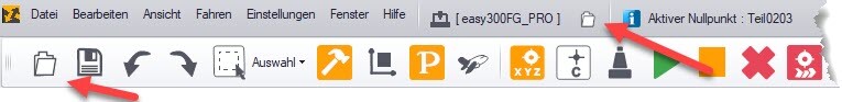
Load file: You can either load the DXF file via the „File -> Open“ menu or by clicking on the „Open file“ icon at the top of the window frame (see screenshot below).
Dialogue window „File properties“: The dialogue window „File properties“ appears first. Here you can set the sheet resolution (medium is recommended) and define the unit. As DXF is always at a scale of 1:1, the unit is „freely definable“ and should be set to 1.
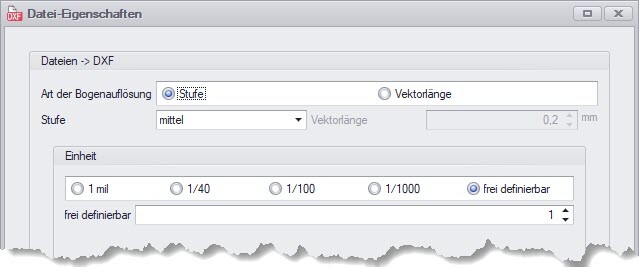
![]() Hinweis: Wenn das Dialogfenster „Datei-Eigenschaften“ nicht erscheint, dann gelangen Sie zu diesem Fenster, indem Sie im Menü den Pfad „Hauptmenü -> Einstellungen -> Optionen -> Datei -> DXF“ verfolgen.
Hinweis: Wenn das Dialogfenster „Datei-Eigenschaften“ nicht erscheint, dann gelangen Sie zu diesem Fenster, indem Sie im Menü den Pfad „Hauptmenü -> Einstellungen -> Optionen -> Datei -> DXF“ verfolgen.
Dialogue window „DXF layer“: The dialogue window „DXF layer“ then appears, in which the layers of the DXF file are displayed. A tool number can be assigned to each layer. A layer can also be excluded for import.
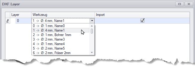
![]() Hinweis: Wenn der Layername dem Namen des Werkzeugs im Werkzeuglager entspricht, dann wird direkt die richtige Werkzeugnummer zugewiesen.
Hinweis: Wenn der Layername dem Namen des Werkzeugs im Werkzeuglager entspricht, dann wird direkt die richtige Werkzeugnummer zugewiesen.
4. milling the DXF file - How to prepare the DXF file.
cncGraF is not comparable with extensive CAD/CAM programmes, as cncGraF is a milling software. Nevertheless, it enables the direct milling of 2D DXF files. The programme offers a selection of useful functions that cannot be covered in detail in this article, as it would go beyond the scope of this article. This article serves as a guide to explain the procedure by way of example.
We use a simple DXF drawing as an illustration: a rectangle with an inner contour and a layer. This drawing was intentionally provided with errors. In the course of this article, we will show how these errors can be identified and corrected.
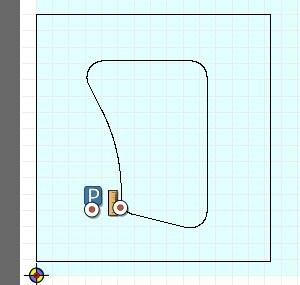
Recognising an unclosed contour
The first thing to check is whether the inner contour and the rectangle of the drawing are closed polylines. The closed polylines are required to be able to perform tool correction.
![]() Hinweis: Die Werkzeugkorrektur kompensiert den Fräserdurchmesser und stellt sicher, dass das gefräste Teil genau den CAD-Vorgaben entspricht.
Hinweis: Die Werkzeugkorrektur kompensiert den Fräserdurchmesser und stellt sicher, dass das gefräste Teil genau den CAD-Vorgaben entspricht.
Recognising an unclosed polyline
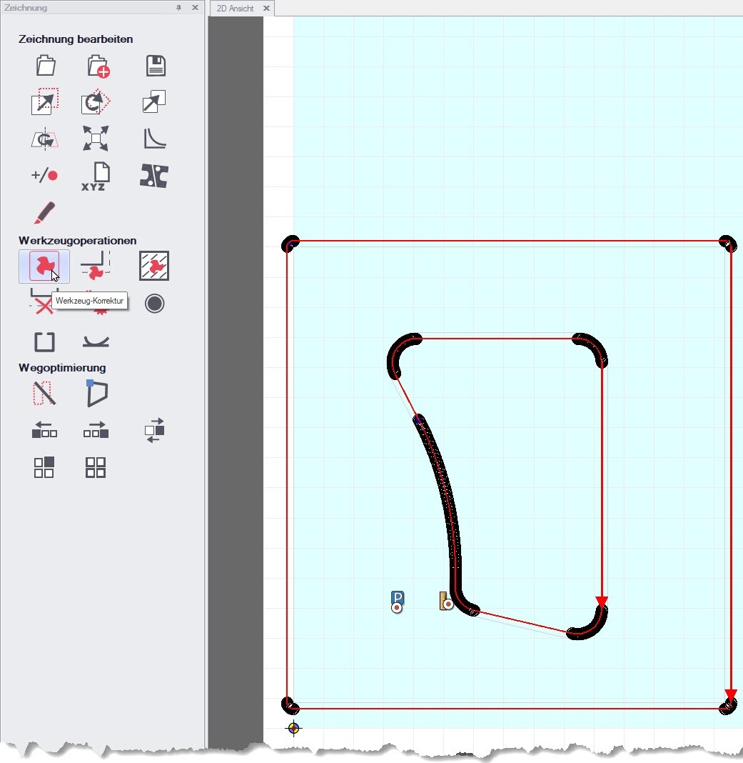
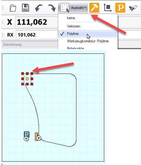
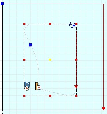
- Check with „Polyline“ selection: If the entire inner contour is not captured by the mouse selection, then there is no closed polyline (see screenshot below left).
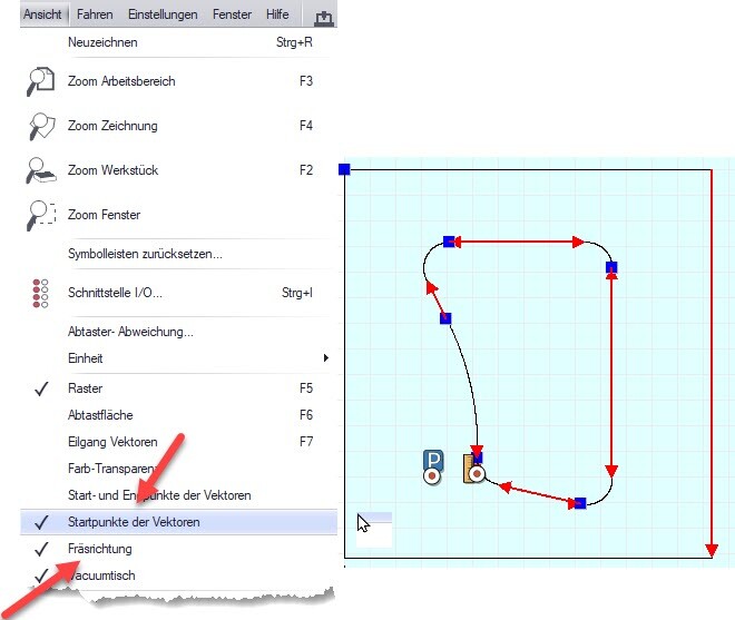
- Check with milling direction indicator: Several red arrows and starting points in the form of blue squares indicate that the contour is not closed (see screenshot below right).
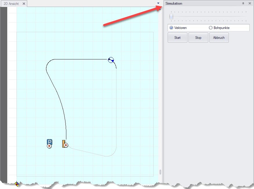
- Check with simulation: The simulation makes it possible to check the processing sequences. This allows you to visually monitor how the milling machine processes the inner contour. To display the simulation window, click on „Window -> Simulation“ in the main menu.
Sort and close unclosed contour
It was determined that the inner contour consists of many individual lines that are drawn in different sequences and directions. This contour would therefore be milled in several sections instead of in one continuous pass.
Combine individual lines into a closed polyline
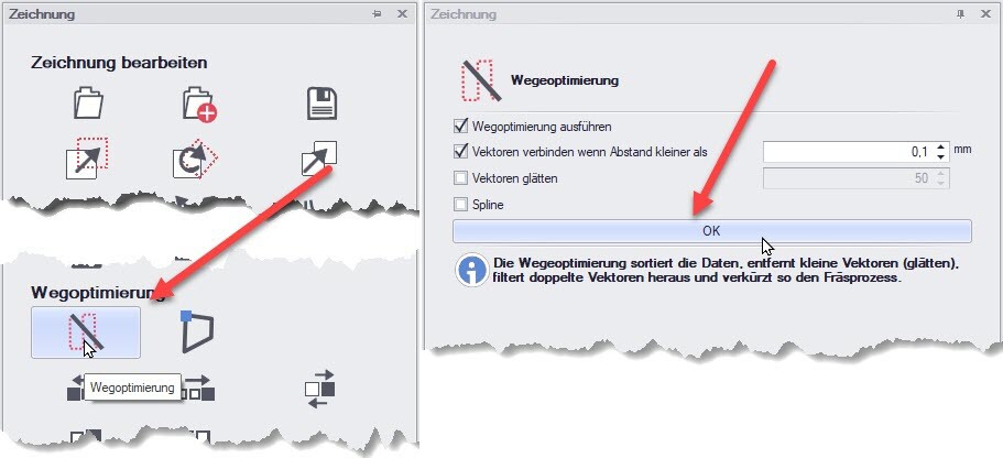
With the „Optimise path“ function, the individual lines of the inner contour can be sorted and automatically connected to form a closed polyline. You will find this function in the drawing window, which can be accessed via the main menu „Window -> Drawing“ (see screenshot below).
After performing the path optimisation, the inner contour only shows a starting point and a red arrow for the milling direction. Both indicators confirm that it is now a single polyline. In addition, the entire inner contour is captured when selecting -> Polyline (see screenshot below).
Creating the tool offset
In our example drawing, there is only one layer and therefore only one tool number. The „Tool correction“ dialogue allows you to set only one correction direction per tool number - either
‚closed on the inside‘ or ‚closed on the outside‘.
- Internal contour: To ensure the original dimensions of the internal contour, the milling path must be offset inwards.
- Rectangle: To achieve the desired dimensions, the milling path of the rectangle must be offset outwards.
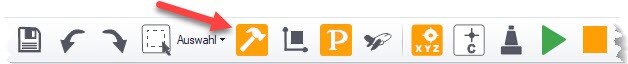
Firstly, we define the tool diameter in the tool store by clicking on the hammer symbol in the toolbar. We then enter the tool diameter in the ‚Tool properties‘ area of the tool store, e.g. 2 mm.
Assigning the tool offset for the polyline
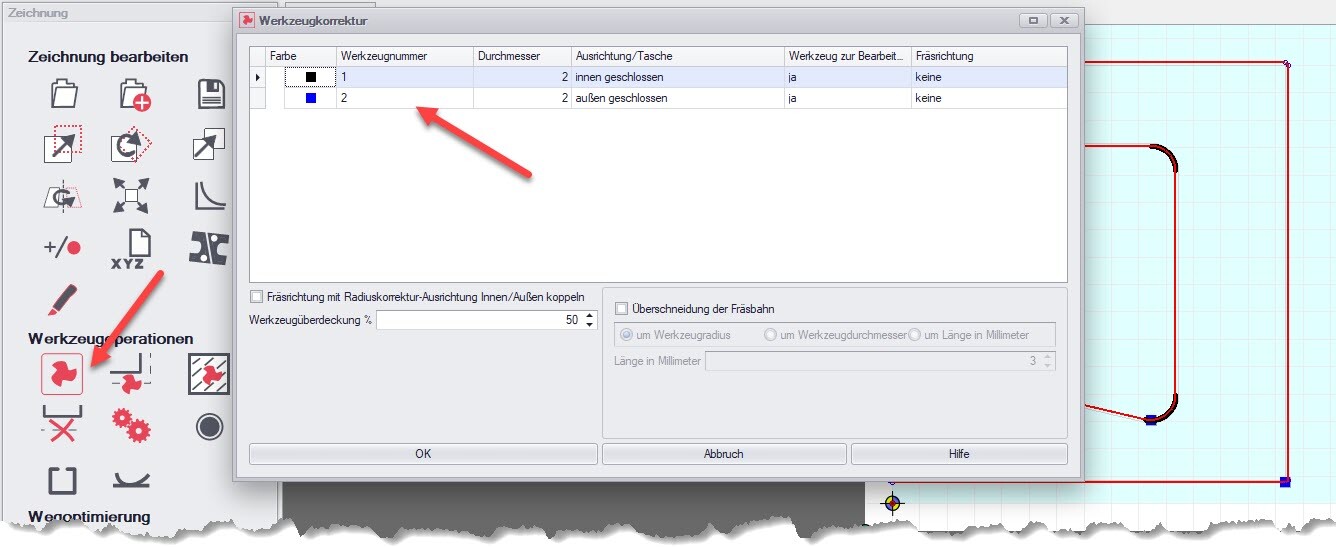
With the „Tool correction for polyline“ function, the tool correction can be assigned to each polyline individually. This function is located in the drawing window, accessible via the main menu „Window -> Drawing“ (see screenshot below, left-hand area).
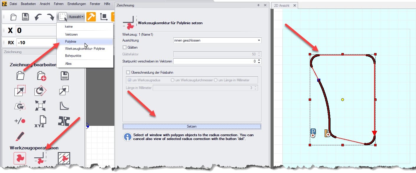
Proceed as follows (see screenshot above):
- Use the mouse to select the desired polyline via Selection-> Polyline.
- In the „Set tool correction for polyline“ dialogue, specify the alignment, e.g. ‚closed inside‘.
- Click on the „Set“ button to set the tool correction.
![]() Note: Several DXF layers are required to automatically perform the tool correction for the entire drawing, which should be assigned to different tool numbers (see point 2: Note drawing rules). For example, the correction ‚closed on the inside‘ can be used for tool 1 and ‚closed on the outside‘ for tool 2.
Note: Several DXF layers are required to automatically perform the tool correction for the entire drawing, which should be assigned to different tool numbers (see point 2: Note drawing rules). For example, the correction ‚closed on the inside‘ can be used for tool 1 and ‚closed on the outside‘ for tool 2.
Another option, especially with larger files, is to check which type of tool correction is required more often - for example, if the tool correction ‚closed on the outside‘ is predominantly required.
In this case, the entire drawing would be calculated with ‚closed on the outside‘. Elements that were calculated incorrectly as a result can be selected with the selection rectangle ‚Tool correction polyline‘ and removed by pressing the ‚ESC‘ key. The correct radius correction for these elements can then be set manually using the method described above.
Determine milling sequence
Before you start milling, it is important to determine the milling sequence. The processing sequence can be checked via the main menu „Window -> Drawing“ using the „Display processing sequences“ function (see screenshot below).
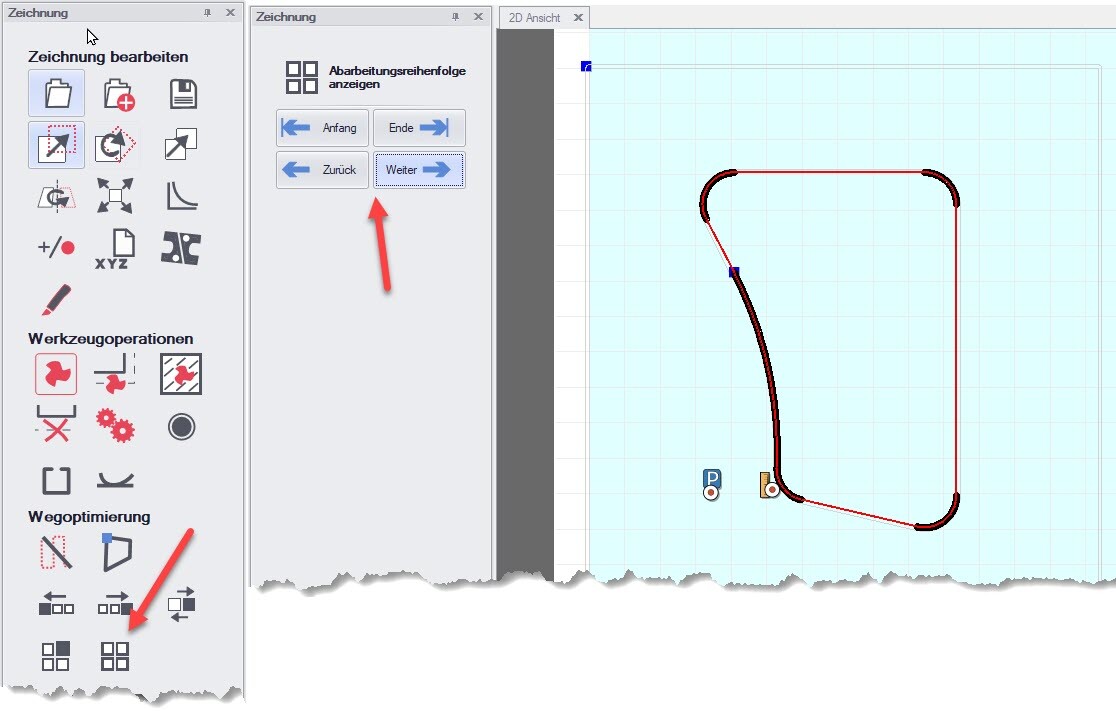
If the processing sequence is not correct, it must be corrected. Our example drawing shows a rectangle as an outline and an inner contour. In this case, the rectangle (outer contour) should be milled last. If the rectangle (outer contour) is machined first, the workpiece could fall out before the inner contour is completely milled.
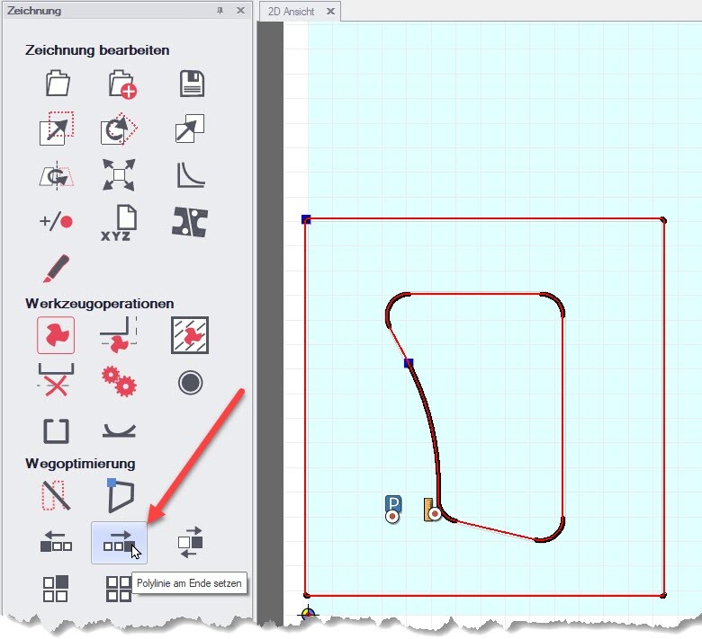
To set the rectangle (outer contour) at the end of the milling process, the ‚Set polyline at end‘ function must be selected. Click on the ‚Set‘ button to activate the selection. Now all you have to do is click on the rectangle in the drawing (see screenshot below).
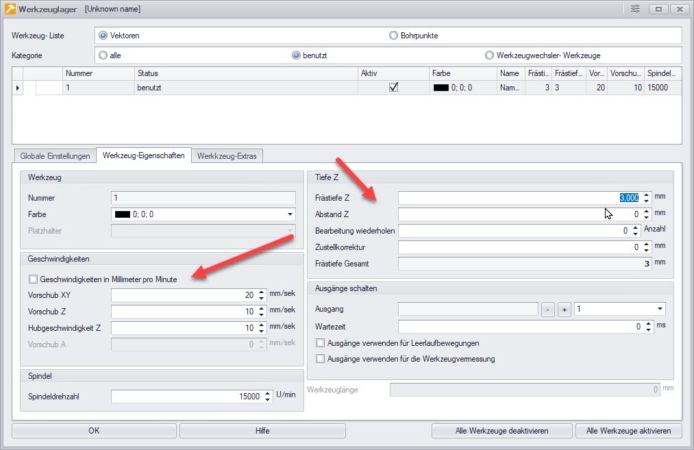
Specifying the milling depth and milling speed
A few settings must be made before milling can begin. These include the milling speed, the spindle speed and the milling depth (optionally with infeed). These parameters can be set in the „Tool storage“ dialogue (see screenshot below).
Milling DXF file
The DXF sample file is now ready to be milled. Before you start the milling process, a zero point must be defined. The zero point is determined by touching the material surface with the milling cutter. Once you have defined the start position (in the bottom left-hand corner of the workpiece), the zero point can be saved in the main menu under „Settings -> Positions“. Alternatively, you can also click directly on the „Set zero point“ icon to define the zero point.
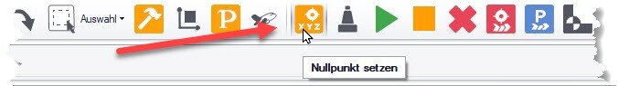
![]() Hinweis: Es gibt natürlich auch weitere Methoden, um einen Nullpunkt festzulegen. In diesem Blog-Artikel beschränken wir uns jedoch auf eine einfache Methode. Das Thema „Nullpunkt setzen“ werden wir in einem anderen Blog-Artikel gesondert behandeln.
Hinweis: Es gibt natürlich auch weitere Methoden, um einen Nullpunkt festzulegen. In diesem Blog-Artikel beschränken wir uns jedoch auf eine einfache Methode. Das Thema „Nullpunkt setzen“ werden wir in einem anderen Blog-Artikel gesondert behandeln.
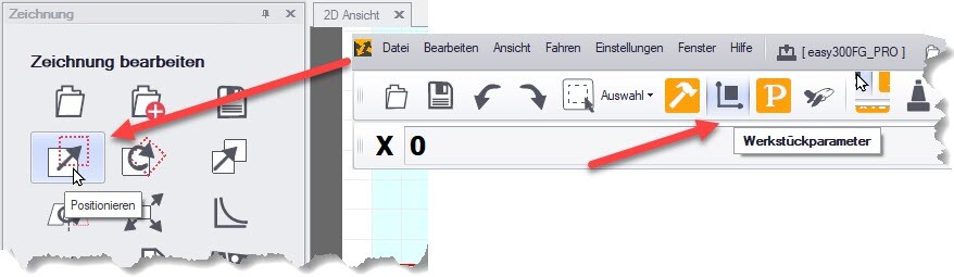
Finally, the drawing should be positioned. This is done using the „Position“ function, which is located in the „Drawing“ window. The display of the workpiece can be used as a guide. This function can be accessed and set either in the toolbar via „Workpiece parameters“ or in the main menu under „Settings -> Workpiece parameters“.
Summary
Milling combines artistic craftsmanship with technical precision. In this article, you have learnt how to achieve precise milling results with targeted preparation. We have highlighted the importance of DXF drawing rules and shown how to import a DXF file into cncGraF. The entire process of preparing a DXF file for milling was also explained in detail - from correcting unclosed contours to tool correction and setting the milling depth and speed.
This guide will provide you with a solid foundation for tackling the challenges of milling.
We hope that with this information you are well equipped to successfully realise your next milling project. Good luck and see you next time!
Yours sincerely, Your BOENIGK-electronics Team